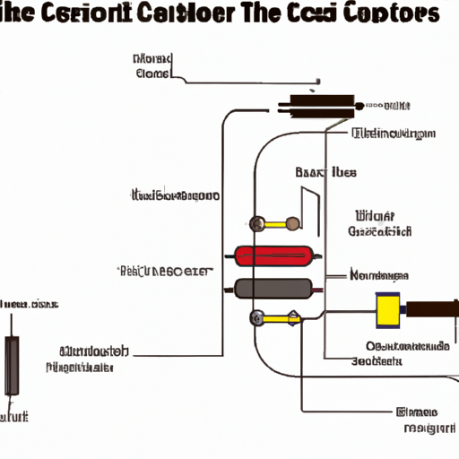
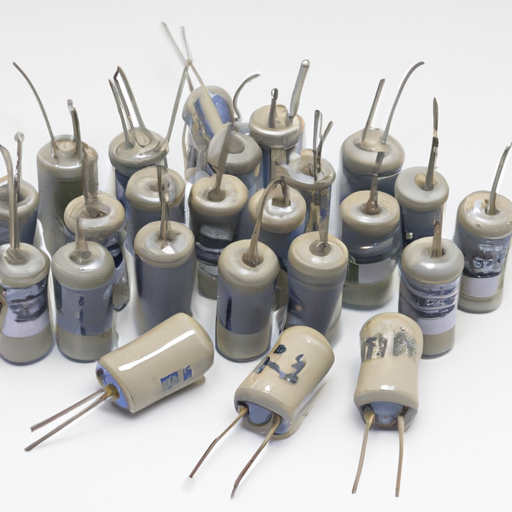
What components and modules are included in the capacitor wiring diagram?
What Components and Modules are Included in the Capacitor Wiring Diagram?
I. Introduction
Capacitors are fundamental components in electrical engineering, playing a crucial role in various circuits and applications. A capacitor is a passive electronic component that stores electrical energy in an electric field, allowing it to release that energy when needed. Understanding how to wire capacitors correctly is essential for engineers and hobbyists alike, as improper wiring can lead to circuit failure or damage. This article aims to explore the components and modules included in capacitor wiring diagrams, providing a comprehensive overview for those looking to deepen their knowledge in this area.
II. Overview of Capacitors
A. Basic Function of Capacitors
Capacitors serve several functions in electrical circuits, including energy storage, filtering, and timing. They can smooth out voltage fluctuations, store energy for later use, and even help in signal processing. When a voltage is applied across a capacitor, it charges up, and when the voltage is removed, it can discharge, providing power to the circuit.
B. Types of Capacitors
There are several types of capacitors, each with unique characteristics and applications:
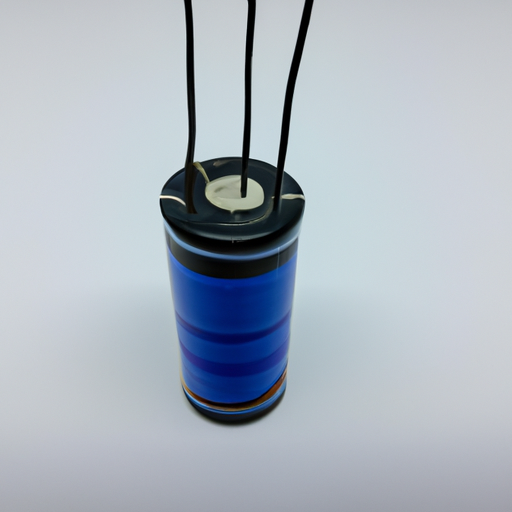
1. **Electrolytic Capacitors**: These are polarized capacitors that offer high capacitance values in a relatively small package. They are commonly used in power supply circuits for smoothing and filtering.
2. **Ceramic Capacitors**: Known for their stability and reliability, ceramic capacitors are often used in high-frequency applications. They come in various capacitance values and are non-polarized.
3. **Film Capacitors**: These capacitors use a thin plastic film as the dielectric. They are known for their low loss and high stability, making them suitable for audio and RF applications.
4. **Tantalum Capacitors**: Similar to electrolytic capacitors, tantalum capacitors are also polarized but offer better performance in terms of size and reliability. They are often used in compact electronic devices.
C. Applications of Capacitors in Circuits
Capacitors are used in a wide range of applications, including power supply circuits, audio equipment, radio frequency circuits, and timing circuits. They can filter out noise, stabilize voltage levels, and store energy for quick release, making them indispensable in modern electronics.
III. Key Components in a Capacitor Wiring Diagram
A. Capacitor
1. **Description and Function**: The capacitor is the primary component in the wiring diagram, responsible for storing and releasing electrical energy.
2. **Symbol Representation in Diagrams**: In wiring diagrams, capacitors are typically represented by two parallel lines, with one line often curved to indicate polarity in polarized capacitors.
B. Resistors
1. **Role in Capacitor Circuits**: Resistors are used to limit current flow and control voltage levels in circuits involving capacitors. They can also help discharge capacitors safely.
2. **Symbol Representation**: Resistors are represented by a zigzag line in wiring diagrams.
C. Inductors
1. **Interaction with Capacitors**: Inductors store energy in a magnetic field and can work in conjunction with capacitors to form resonant circuits, which are essential in tuning applications.
2. **Symbol Representation**: Inductors are depicted as a series of loops or coils in diagrams.
D. Diodes
1. **Function in Capacitor Circuits**: Diodes allow current to flow in one direction only, protecting capacitors from reverse polarity and preventing damage.
2. **Symbol Representation**: Diodes are represented by a triangle pointing towards a line in wiring diagrams.
E. Transistors
1. **Use in Conjunction with Capacitors**: Transistors can amplify signals and switch currents, often working alongside capacitors in timing and filtering applications.
2. **Symbol Representation**: Transistors are represented by a combination of lines and circles, indicating their type (NPN or PNP).
IV. Modules in a Capacitor Wiring Diagram
A. Power Supply Module
1. **Description and Function**: The power supply module provides the necessary voltage and current to the circuit, ensuring that capacitors can charge and discharge effectively.
2. **Importance in Capacitor Circuits**: A stable power supply is crucial for the proper functioning of capacitors, as fluctuations can lead to circuit instability.
B. Control Module
1. **Role in Managing Capacitor Functions**: Control modules regulate the operation of capacitors, ensuring they charge and discharge at the correct times.
2. **Examples of Control Modules**: Microcontrollers and timers are common examples that manage capacitor functions in various applications.
C. Signal Processing Module
1. **Interaction with Capacitors**: Signal processing modules often use capacitors to filter and shape signals, improving the quality of audio and communication systems.
2. **Applications in Circuits**: Capacitors in signal processing modules can help eliminate noise and enhance signal clarity.
D. Protection Module
1. **Importance of Protection in Capacitor Circuits**: Protection modules safeguard capacitors from overvoltage and reverse polarity, preventing damage and ensuring longevity.
2. **Common Protection Components**: Fuses, circuit breakers, and transient voltage suppressors are commonly used in protection modules.
V. Wiring Techniques and Best Practices
A. Proper Connections and Soldering Techniques
When wiring capacitors, it is essential to ensure that connections are secure and soldered correctly. Poor connections can lead to circuit failure or intermittent issues.
B. Importance of Polarity in Capacitor Wiring
For polarized capacitors, such as electrolytic and tantalum types, it is crucial to connect them with the correct polarity. Reversing the connections can lead to capacitor failure or even explosion.
C. Common Mistakes to Avoid
Some common mistakes include using the wrong type of capacitor, neglecting to account for voltage ratings, and failing to discharge capacitors before working on a circuit.
D. Safety Considerations When Working with Capacitors
Capacitors can store significant amounts of energy, posing a risk of electric shock. Always discharge capacitors before handling them and use appropriate safety gear.
VI. Reading and Interpreting Capacitor Wiring Diagrams
A. Understanding Symbols and Notations
Familiarizing yourself with the symbols used in wiring diagrams is essential for effective interpretation. Each component has a specific symbol that conveys its function.
B. Step-by-Step Guide to Reading a Wiring Diagram
1. Identify the power source and its connections.
2. Trace the path of current flow through the circuit.
3. Note the arrangement of components, including capacitors, resistors, and other modules.
4. Pay attention to polarity and connections.
C. Examples of Common Capacitor Wiring Diagrams
Common examples include power supply circuits, audio filter circuits, and timing circuits, each demonstrating the role of capacitors in different applications.
VII. Conclusion
Understanding capacitor wiring diagrams is vital for anyone involved in electrical engineering or electronics. By familiarizing yourself with the components and modules included in these diagrams, you can design and troubleshoot circuits more effectively. As technology continues to evolve, the role of capacitors in modern electronics will only grow, making it essential to continue learning and practicing in this field.
VIII. References
A. Suggested readings and resources for further learning include textbooks on electrical engineering, online courses, and tutorials focused on capacitors and circuit design.
B. Relevant websites and online courses can provide additional insights and practical knowledge, helping you to deepen your understanding of capacitors and their applications in various circuits.
By exploring these resources, you can enhance your skills and knowledge, paving the way for a successful journey in the world of electronics.

