What components and modules are included in capacitor grounding?
What Components and Modules are Included in Capacitor Grounding?
I. Introduction
Capacitor grounding is a critical aspect of electrical systems that ensures safety, reliability, and efficiency. Grounding refers to the process of connecting electrical equipment to the earth or a conductive body that serves as a reference point for voltage. This connection is vital for protecting both equipment and personnel from electrical faults. In this article, we will explore the components and modules involved in capacitor grounding, emphasizing their roles and importance in maintaining safe electrical operations.
II. Understanding Capacitors
A. Basic Principles of Capacitors
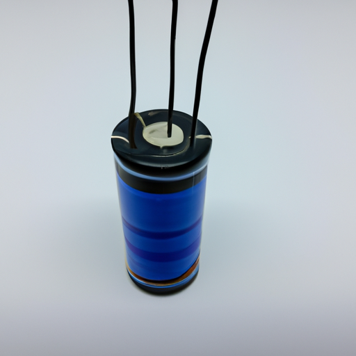
Capacitors are passive electrical components that store and release electrical energy. They consist of two conductive plates separated by an insulating material known as a dielectric. When a voltage is applied across the plates, an electric field is created, allowing the capacitor to store energy.
1. **Definition and Function**: Capacitors are used to store electrical energy temporarily and release it when needed. They play a crucial role in various applications, including power supply smoothing, signal coupling, and energy storage in power systems.
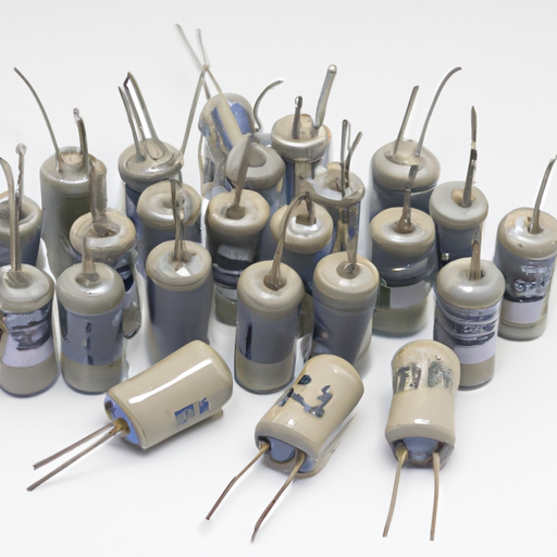
2. **Types of Capacitors**: There are several types of capacitors, including ceramic, electrolytic, tantalum, and film capacitors. Each type has unique characteristics that make it suitable for specific applications.
B. Role of Capacitors in Electrical Systems
Capacitors serve multiple functions in electrical systems:
1. **Energy Storage**: Capacitors can store energy for short periods, making them essential in applications like power factor correction and energy buffering.
2. **Filtering and Smoothing**: In power supply circuits, capacitors help filter out voltage spikes and smooth the output voltage, ensuring stable operation.
3. **Power Factor Correction**: Capacitors improve the power factor of electrical systems by compensating for inductive loads, reducing energy losses, and enhancing system efficiency.
III. The Concept of Grounding
A. Definition of Grounding in Electrical Systems
Grounding is the process of connecting electrical equipment to the earth or a conductive body to establish a reference point for voltage. This connection helps prevent electrical shock, equipment damage, and fire hazards.
B. Importance of Grounding for Safety and Performance
Grounding is essential for several reasons:
Safety: It protects personnel from electrical shock by providing a low-resistance path for fault currents to flow to the ground.
Equipment Protection: Grounding helps prevent damage to electrical equipment by diverting excess voltage and current away from sensitive components.
System Performance: Proper grounding enhances the performance of electrical systems by reducing electromagnetic interference and ensuring stable operation.
C. Types of Grounding Systems
1. **System Grounding**: This involves connecting the neutral point of a power system to the ground, providing a reference point for voltage and enhancing system stability.
2. **Equipment Grounding**: This type of grounding connects the non-current-carrying parts of electrical equipment to the ground, ensuring safety in case of insulation failure.
3. **Functional Grounding**: This grounding method is used for specific functions, such as signal reference in communication systems.
IV. Components of Capacitor Grounding
A. Grounding Electrode System
The grounding electrode system is a crucial component of capacitor grounding, consisting of various elements that establish a connection to the earth.
1. **Ground Rods**: These are metal rods driven into the ground to provide a low-resistance path for fault currents. They are typically made of copper or galvanized steel.
2. **Ground Plates**: Ground plates are large metal plates buried in the ground to enhance the grounding system's effectiveness, especially in areas with high soil resistivity.
3. **Grounding Conductors**: These are wires that connect the grounding electrodes to the electrical equipment, ensuring a reliable path for fault currents.
B. Grounding Busbars
Grounding busbars are conductive bars that serve as a common connection point for multiple grounding conductors.
1. **Definition and Function**: Busbars provide a centralized location for connecting various grounding points, simplifying the grounding system's design and installation.
2. **Connection to Multiple Grounding Points**: By using busbars, electrical engineers can efficiently connect multiple pieces of equipment to the grounding system, ensuring uniform grounding across the system.
C. Grounding Switches
Grounding switches are devices that allow operators to connect or disconnect equipment from the grounding system.
1. **Purpose and Operation**: These switches enable safe maintenance and operation of electrical equipment by providing a means to isolate equipment from the grounding system.
2. **Safety Features**: Grounding switches often include safety interlocks to prevent accidental operation while the equipment is energized.
D. Surge Protection Devices (SPDs)
Surge protection devices are essential for protecting capacitors from voltage spikes caused by lightning strikes or switching operations.
1. **Role in Protecting Capacitors**: SPDs divert excess voltage away from capacitors, preventing damage and ensuring their longevity.
2. **Types of SPDs**: There are various types of SPDs, including metal-oxide varistors (MOVs) and gas discharge tubes (GDTs), each designed for specific applications and voltage levels.
E. Ground Fault Protection Devices
Ground fault protection devices are critical for detecting and interrupting ground faults in electrical systems.
1. **Importance in Capacitor Grounding**: These devices help prevent electrical shock and equipment damage by quickly disconnecting the power supply in the event of a ground fault.
2. **Types and Functions**: Ground fault circuit interrupters (GFCIs) and residual current devices (RCDs) are common types of ground fault protection devices used in capacitor grounding systems.
V. Modules Involved in Capacitor Grounding
A. Capacitor Banks
Capacitor banks are assemblies of multiple capacitors connected in parallel or series to achieve desired capacitance levels.
1. **Definition and Purpose**: Capacitor banks are used for power factor correction, voltage regulation, and energy storage in electrical systems.
2. **Grounding Requirements for Capacitor Banks**: Proper grounding is essential for capacitor banks to ensure safety and prevent damage from electrical faults.
B. Control Panels
Control panels play a vital role in monitoring and controlling grounding systems.
1. **Role in Monitoring and Controlling Grounding**: Control panels provide operators with real-time data on grounding system performance, allowing for timely interventions when issues arise.
2. **Integration with Grounding Systems**: Modern control panels can integrate with grounding systems to automate monitoring and control functions, enhancing system reliability.
C. Monitoring Systems
Monitoring systems are essential for ensuring the effectiveness of grounding systems.
1. **Importance of Real-Time Monitoring**: Continuous monitoring of grounding systems helps identify potential issues before they escalate, ensuring safety and reliability.
2. **Types of Monitoring Systems Used**: Various monitoring technologies, including ground resistance testers and continuous monitoring devices, are employed to assess grounding system performance.
VI. Best Practices for Capacitor Grounding
A. Design Considerations
1. **Proper Sizing of Grounding Components**: Ensuring that grounding components are appropriately sized for the application is crucial for effective grounding.
2. **Material Selection**: Choosing the right materials for grounding components can enhance their performance and longevity.
B. Installation Guidelines
1. **Techniques for Effective Grounding**: Following best practices during installation, such as ensuring proper connections and minimizing resistance, is essential for effective grounding.
2. **Common Pitfalls to Avoid**: Avoiding common mistakes, such as inadequate grounding electrode depth or improper conductor sizing, can prevent grounding system failures.
C. Maintenance and Testing
1. **Regular Inspections**: Conducting regular inspections of grounding systems helps identify potential issues and ensures compliance with safety standards.
2. **Testing Grounding Effectiveness**: Periodic testing of grounding systems, including ground resistance testing, is essential for verifying their effectiveness.
VII. Conclusion
In conclusion, capacitor grounding is a vital aspect of electrical systems that ensures safety, reliability, and efficiency. Understanding the components and modules involved in capacitor grounding, such as grounding electrode systems, busbars, switches, surge protection devices, and ground fault protection devices, is essential for effective system design and operation. By following best practices in design, installation, and maintenance, electrical engineers can ensure the safety and efficiency of their systems, ultimately contributing to a more reliable electrical infrastructure.
VIII. References
- National Electrical Code (NEC)
- Institute of Electrical and Electronics Engineers (IEEE) Standards
- International Electrotechnical Commission (IEC) Guidelines
- Various technical publications on grounding practices and capacitor technology
This comprehensive overview of capacitor grounding highlights the importance of proper grounding practices in electrical systems, ensuring safety and efficiency in their operation.


